Assessing the quality of your parts can be difficult if you aren’t using the best technology for the job. In this article, we’ll discuss the different methods of metrology used for part inspection and how 3D scanning parts for CNC machining can be beneficial for quality assurance, quality control, and tooling inspection.
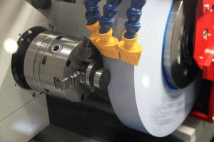 Machining and Metrology
Metrology is a critical part of any manufacturing process, especially where quality assurance and quality control are concerned. Measurements have traditionally been taken with hand tools, such as calipers and micrometers, and more recently, coordinate measuring machines (CMM).
CMM probes are touch probes that are manually or mechanically touched to the surface of your part. The coordinates of the point where the probe makes contact is recorded, and the process is repeated until enough data points are collected. Since the data points are collect one at a time, the amount of resulting measurements is subject to how much time is devoted to the part. As such, only a limited number of measurements are typically collected.
Despite the time-consuming task of a CMM probe, this technology is more accurate than any 3D scanner and can measure down to 0.00001” as opposed to the typical 3D scanner’s point accuracy of 0.001”. However, the precision offered by CMM may be more than your parts require. Injection molded parts, for example, can’t hold tolerances nearly as high as a CMM can measure. In such cases, it may be more efficient to use a 3D scanner.
CMM analysis is much more practical for CNC machined parts, which can hold much higher tolerances. However, if measurements of an entire part are needed for your part inspection requirements, 3D scanning might be the more efficient choice over CMM probing.
3D Scanning CNC Machined Parts
Like CMM probes, the most common application for 3D scanning is dimensional inspection for quality assurance and control. The main advantage to 3D scanning is that thousands of data points can be captured from a part in a matter of seconds. Depending on the part’s size and complexity, a complete scan can be generated in a fraction of the time that it would take to touch off a handful of points. The result of this scan is that a whole part can be checked for accuracy against the original CAD and can even be reverse engineered if necessary.
Most machined parts are readily scanned. The main area where the scans can get tricky is with metal parts that are shiny or reflective. This is because most 3D scanners involve some type of light pattern or laser, and shiny and reflective surfaces will scatter and distort the light. This makes the scans unusable since the measurements taken will not be reliable.
There are several types of 3D scanning technologies. Below, we’ll examine how each technology works and how each performs with metal machined parts.
 Structured Light Scanning
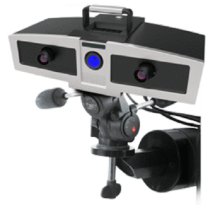
Structured light 3D scanners take high resolution scans by projecting various light patterns onto a part and recording where and how the pattern is distorted. This data is recorded when the cameras take a “shot” of the surface that is facing the projector. Shots are taken from every side of the object and compiled to create the 3D scan. While not the fastest method of scanning, structured light scanners provide one of the highest accuracies available, which is necessary when assessing machined parts. With a minimum feature size of 0.0002” and a small field of vision, structured light scanners work best with small parts and fine details.
It is important to note that structured light scanners do not perform well with metal parts that are shiny or reflective. In order to produce a quality scan in such cases, metal parts must go through pre-processing where they are coated with a washable paint. Metal parts that are unable to be painted must use a different scanning technology, which will result in a loss of accuracy in the scan.
 Laser Scanning
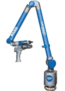
Laser scanners are a faster, though less accurate, method of producing a 3D scan. These scanners use a laser point or laser line to record data points as they are run over an object’s surface. The Faro laser scanner that we offer in-house is mounted to a moveable arm, giving the scanning technician more mobility to reach multiple different angles on a part. Even difficult to reach areas are able to be scanned with ease. Given this mobility, the Faro scanner can handle larger parts. As opposed to the structured light scanner, laser scanners do not often struggle with shiny or reflective parts, so your metal machined parts do not have to be coated to be scanned with this technology.
The Faro laser scanner also includes a touch probe, which utilizes technology similar to CMM. While it’s not as accurate as a CMM probe, it is more accurate than the laser scanner and can provide additional data for critical dimensions. This additional feature can operate separately or in tandem with its laser counterpart, allowing you the best of both worlds as you can use a blend of both 3D scanning and CMM technology.
CT Scanning
Computed tomography (CT) scanning is great if your parts have internal geometry that cannot be measured without destructive methods. CT scanners use X-rays to take 2D slices of your part and then compile them to create a 3D image. CT scanners offer point accuracy down to 0.0001”, which is much higher than most optical scanners. This increased accuracy comes at a cost, however, as the equipment is significantly more expensive. The speed of the CT process is determined by the density of the part. The more dense a part is, the harder it may be for the X-rays to pass through it.
As for machined parts, metal can cause problems for CT scanning. Metal absorbs X-rays, which will cause the scan to appear streaked at the point where the X-rays come in contact with the metal barrier. This streaking often obscures the surrounding areas in the scan so much that good measurements cannot be procured for part inspection. However, non-metal machined parts with internal geometry will greatly benefit from CT scanning.
Types of Part Inspection
3D scanning produces excellent data that can be used for part inspection. This includes quality assurance, quality control, and tooling inspection, all of which are crucial in guaranteeing your part is produced the way you intended.
Quality Assurance
3D scanning can make your QA processes much more efficient since measurements can be taken more quickly than a CMM probe. Since a 3D scan records thousands of data points from your part, all areas of your part can be checked for deviation from the design. This is done using a color map to determine where and how much a part is out of tolerance from the original CAD. If there is a defect trend evident in the color maps from several parts, you can then determine where and how to adjust your machining process to correct these.
 Quality Control
Quality control benefits from 3D scanning in the same way as quality assurance. Scans of selected sample parts from the batch can be scanned and compared to the original CAD to identify defect trends that can then be corrected back in the production process. For machined parts in particular, this can help you identify if your cutting tool has become worn.
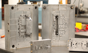
Tooling Inspection
Over time, injection molds may become worn and need to be reevaluated for accuracy. If you’ve discovered your injection molded parts are out of spec but aren’t sure what is the source of the defect, it may be a good idea to 3D scan the mold itself. By doing so, you can determine whether the mold has become worn and has developed any areas that may produce part deformities, such as cracks or similar damages in the mold.
3D Scanning at 3 Space
At 3 Space, we utilize structured light, laser, touch probe, and CT scanners to produce top quality scans for our customers. Our engineers have years of experience in 3D scanning, reverse engineering, and part inspection reports. As such, they can provide an expert opinion on what scanning technology will work best for your part. Contact us for more information.