Design intent refers to a designer’s specifications of how a part should appear and function. Ideally, when manufactured, the resulting part will match this design exactly. The concept of design intent plays a primary role in reverse engineering, which is a process that works backwards to take measurements from an as-built part and create a usable CAD model for record keeping, design modification, and more.
In this article, we’ll explain how design intent is important to the reverse engineering process, including client to engineer understanding and programming CAD modelling software. Specifically, we will only cover this topic in relation to 3D scanning a part to create CAD.
 As-Built vs. Design Intent
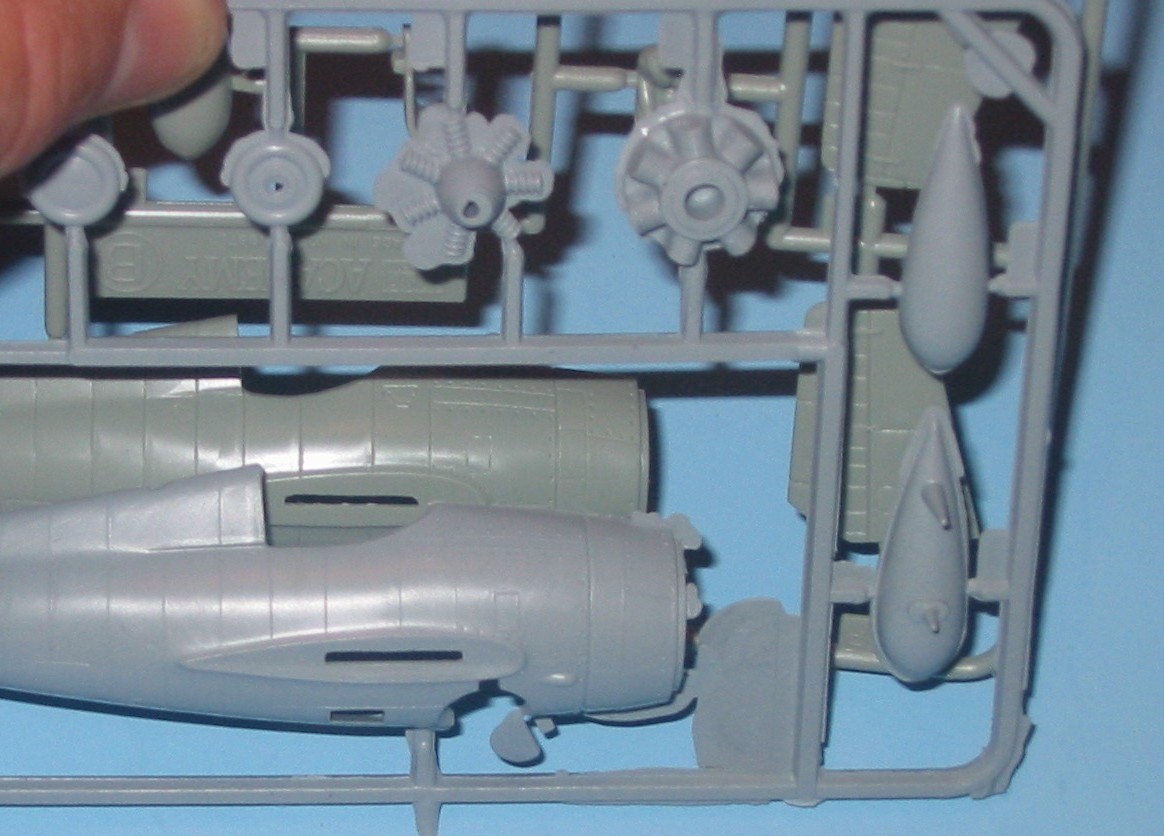
When a part is given to an engineer to 3D scan and reverse engineer, the part arrives as-built. This means that any manufacturing defects, such as sink, warp, flash, ejector pin indention, and more, may be present in the part. Wear, such as scratches, twisting, bending, or breakage, may also be apparent. Neither manufacturing defects nor wear are ever part of the intended design, but they cannot be avoided. Manufacturing defects will always occur in a part. Even if the part is only fractions of a millimeter different from the design model, it does not match the design intent.
Reverse engineering is most often used to create a digital CAD file that restores the as-built part to its intended design specifications. However, when 3D scanning the part, the data gathered will reflect the part as-is, and the engineer must adjust the design as needed. If a CAD model were made from the scan of the as-built part, the defects would be built into the new file. This 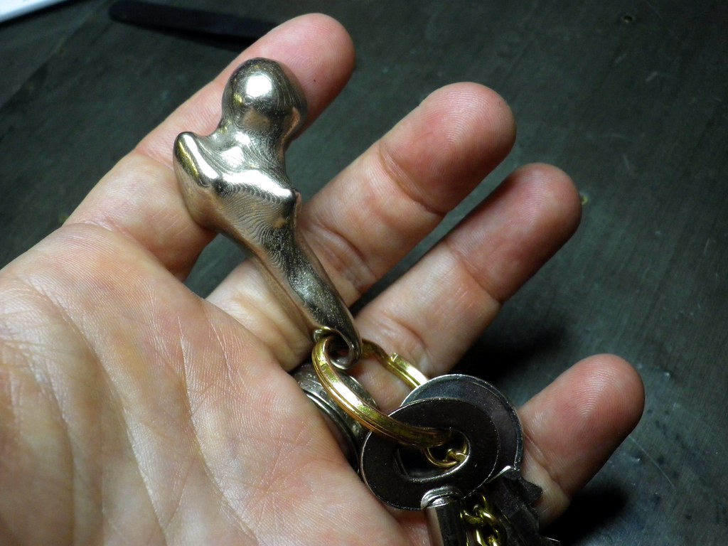 becomes a problem when seeking to manufacture more parts from this model. If, for example, a part that was intended to be 1.00” in length was produced and scanned as 1.01” and then a CAD file was made from this as-built data, future parts could end up being produced as 1.02”. As such, creating CAD files intended for future manufacturing from as-built parts will cause the part to drift off course from the design intent.
It is worth noting that, sometimes, a client may want a part reproduced as-built. For instance, this may occur when they have modified a part and have found it to work better after the manual modification. If they want more of the modified part, they would turn to reverse engineering to create a CAD file of the design as-is. However, this does not happen often and must be communicated to the modelling engineer.
Design Intent in Client to Engineer Communication
Communication between the client and the engineer is easily the most important step of reverse engineering. When given a reverse engineering job, the engineer only knows what they can see from the physical part and any information the client gives them. This includes telling 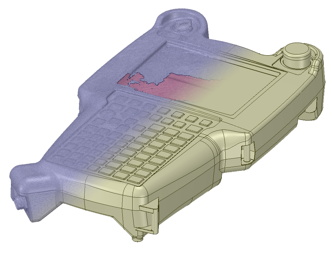 the engineer if the part should be reproduced as-built or with design intent and what that design intent is.
If the part is simple and straightforward, such as a flat plane or symmetrical figure, the engineer can easily infer what needs to be done to bring the part back into spec. Even with some broken parts, such as a missing cog from a gear, the engineer can use logic to recreate the part.
However, if the part is complex and the client has not clearly communicated the part’s design intent, the engineer may be unable to reliably discern what needs to be done to correct the as-built scan. This can lead to confusion and frustration for both parties involved as the engineer can only make educated guesses without the client’s direction.
Design Intent in CAD Software
The engineer is not the only component of the reverse engineering process that needs to know the part’s design intent. The CAD modelling software that is being used must also be told this. This is done by the engineer instructing the program how to treat different features in the file 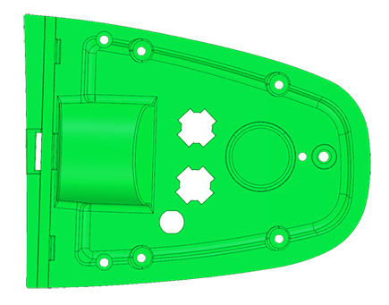 so that it does not change the intentions of the design when modifications are made. For example, if you have a 2×2” part with a 0.5” hole through the center of it and want to lengthen the part to 2×10”, the software will need to know if the hole is to remain centered or be a certain distance from a given edge. These parameters, or constraints, are put in place to help the engineer and ensure that the design intent does not change.
To get a more in-depth look at 3D scan file types and reverse engineering, check out our “3D Scan to CAD” article.
Reverse Engineering at 3 Space
Here at 3 Space, we offer multiple 3D scanning services, including reverse engineering. We work closely with you to ensure the model we give you is exactly what you need. For more information about our reverse engineering services or to receive a quote, contact us today.