When it comes to 3D digital models, it can be a bit confusing to know which model or file type you need. The two primary types of models you will encounter are meshes and CAD files. In this article, we’ll break down the difference between both model types and explain how they are made and how they look and function.
Mesh
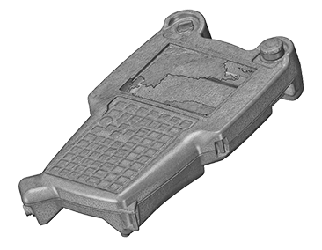
 Appearance & Features
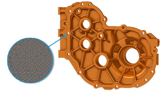
A mesh is a 3D model that is made up entirely of triangles that often number in the thousands or millions to create a complete model. These triangles are made by connecting data points that have been rendered on Cartesian coordinates (X, Y, and Z planes). The points serve as vertices, and once they have all been connected to their immediate neighbor, a full model is formed. For the mesh to work properly, it cannot be self-intersecting, meaning that no line, or edge, can pierce the face of another triangle. This type of model does not distinguish between different features, such as faces or holes, which is one reason why editing a mesh parametrically is very difficult compared to CAD. This model may also be referred to as a polygonal model.
How It’s Made
When a part is 3D scanned, the scanner records measurements in the form of thousands or millions of data points, called a point cloud. These data points become the vertices of the triangles once the software is told to convert the point cloud into a mesh by connecting the dots. A mesh may also be created manually, but this method is tedious and ineffective because an average low-resolution mesh will still have hundreds or thousands of data points.
Applications
Meshes can be used for several different purposes, including the following:
- Reverse engineering – Meshes serve as a template for engineers to draw usable CAD of the scanned part. This is used to replace lost CAD, create CAD for legacy parts, and more.
- Dimensional analysis –
 A mesh can be overlaid onto original CAD to generate a color map that indicates areas of the part that deviate from the CAD and how far the scanned part is out of tolerance. 2D cross-sectional slices may also be generated for this purpose. This can help with FAI, part-to-part comparison, multi-cavity mold/tooling inspection, and more.
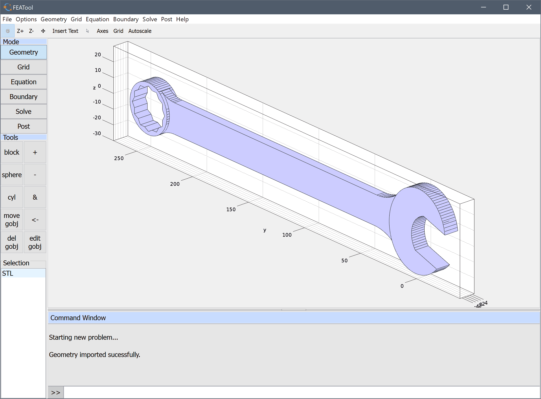
 - 3D printing – Meshes are primarily saved as STL files. An STL is the file type supported by 3D printers, meaning that you can import a mesh to a 3D printer and produce the part from this model.
CAD (Computer-Aided Design)
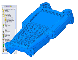
Appearance & Features
CAD is a solid body model that is capable of distinguishing features, such as surfaces and holes. As opposed to a mesh that has triangles that make it difficult to achieve perfect curves and other similar features, CAD is smooth, noise-free, and easily editable.
 There are two types of CAD: suite-specific CAD and generic (“dumb solid”) CAD. Both are identical in appearance, but their editability and file types differ for varied ease of sharing between client and engineer. Suite-specific CAD is tied to the program it is made in and offers full editability within its program. However, because it cannot be opened in any other program and there are so many CAD software programs available, it is not the easiest for exchanging files. Rather, generic CAD is a more universal file type because it is not anchored to one specific program. Unfortunately, saving a suite-specific CAD model as a generic CAD file to make sharing easier comes at the price of editability. It may best be compared to saving a Microsoft Word file as a PDF. The PDF is readable by more programs, but there are fewer editing options than you would have available in Microsoft Word.
How It’s Made
When designing from scratch or reverse engineering, all CAD is suite-specific. It is manually drawn into the program by the engineer either through parametric modelling or direct modelling. Edits can be made easily with either method. For generic CAD to be made, the suite-specific CAD is simply saved as a different file type, usually a STEP or IGES file. If the suite-specific CAD was designed parametrically, this will remove the editable feature tree.
Applications
The two different types of CAD have various applications, which are explained below:
 Design creation – Suite-specific CAD offers a full range of tools that will let you create any model you desire from scratch, including prototypes, tooling, and much more.
 - Design modification – Suite-specific CAD gives you the option to fully modify your design any way you like, while generic CAD gives you limited options for edits.
- Manufacturing – Generic CAD files can be used for traditional manufacturing methods, including machining, injection molding, and more.
- Digital inventory – Generic CAD can be stored on a computer and act as a digital library for product designs that can be printed on-demand.
Digital Modelling at 3 Space
Here at 3 Space, we offer multiple digital modelling services, including 3D scanning, reverse engineering, and product development. Our team of expert engineers is always happy to help get you the model you need. For more information or to receive a quote, contact us today.