Injection molding is a method of mass production manufacturing and is not without its faults. Defects can be minor surface marks or major areas of weakness or failure. They are often the result of errors in the molding process, poor design, material contamination, or a combination of the three.
In this article, we’ll discuss the common defects you may encounter with injection molding, including how to recognize them, what causes them, and how to avoid them.
Black Specks
If the surface of your part appears to have specks, or flakes, of another material embedded in it, you may have a contamination problem with your material. However, if these specks are black, they may indicate a different problem. Often, black specks in parts can be caused by the molten material carbonizing inside the injection molding machine’s barrel. This occurs when the material is kept inside the barrel too long and degrades, causing it to turn black and clump together. To avoid this problem, increase injection speed so the time the material is kept inside the barrel is minimized.
Burn Marks
A part may become burned during molding if the material overheats. This defect is distinguishable from other discoloration issues because it will be black or rust-colored. Severe burns, however, may appear as degraded or destroyed material, not just surface discoloration. Overheating may be caused by insufficient venting or injection speed being too high. Adjusting the venting, injection speed, molding temperature, and cycle time may help negate the possibility for burns marks.
Discoloration
Your part may have uneven coloring or total discoloration if your colorant isn’t properly mixed with your base material or has run low or if your material is otherwise contaminated. Discoloration by contamination is commonly caused by leftover material from previous molding batches residing in the hopper, barrel, or mold. In this case, it is best to thoroughly clean the machine and mold before continuing production.
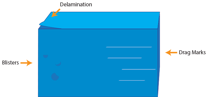
Blisters
Blistering appears as raised or layered areas on a part’s surface and is often caused by a machine or mold that is running too hot. Testing and adjusting the temperature of the machine and/or mold can eliminate this problem. Blisters that are caused by bubbles, or pockets of trapped steam, air, or gas, may be avoided by pre-drying your material and ensuring proper ventilation of the mold.
Delamination
Delamination is what happens when the material does not bond together correctly during molding and the part forms in layers that can be peeled away. This indicates that your part is neither solid nor strong and can easily break. Improper material bonding can happen due to contamination, moisture, overuse of mold release agents, non-compatible materials being combined, and slow injection speed. To correct a material bonding issue, you can check for contaminants in your material stock, pre-dry your material, and reduce the amount of mold release agent used during each cycle. In the case of injection speed being the primary issue, increase it so the material does not have time to cool into separate layers.
Drag Marks
If your part has scratches or gouges in its surface, this may be a sign that the part is dragging against the mold cavity walls as it is being ejected. This ejection difficulty can happen when the designed draft angle is insufficient to accommodate shrinkage and ejection or the mold’s surface finish is perpendicular to the release direction. Unfortunately, this may mean that a redesign and adjustment to the part and mold must be made to increase the draft angle or change the position of the parting line. In some cases, a mold release agent may help to reduce drag.
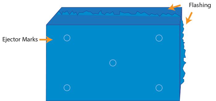
Ejector Marks
Similar to drag marks, ejector marks are a defect that can occur during the ejection phase. These marks appear as indentations where the material has sunk in when the ejector pins press on the part to release it from the mold. This happens when the cooling time is too short and the plastic has not had enough time to harden or when the ejection force is too high. To correct this issue, you can either leave the part in the mold longer or decrease the ejection force. It is important to note that if a lower ejection force doesn’t work to fully push the part out and the part becomes stuck in the mold, your part likely has insufficient draft angles and may be creating a vacuum when the machine tries to eject it. As the machine tries to force out a stuck part, the part may warp or break and the machine itself may be damaged.
Flash
Flash, also called “burrs” or “spew”, is excess material that has flowed outside of the mold. This defect most often appears as thin slivers of material attached to the part where the mold’s parting line is located. Material can escape the mold when the clamping force is too high, the mold halves are misaligned, debris or wear on the mating surfaces keeps it from closing properly, and injection force is too high. Both clamping and injection force can be adjusted as needed to prevent flash. For the mold itself, it should be inspected, cleaned, and repaired or replaced if necessary.
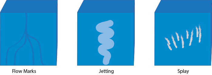
Flow Lines
Flow lines are off-tone color marks in the surface of the part where semi-solid material has been dragged and smeared during the molding process. Typically, these marks occur around gates and, thus, look like misshapen, discolored rings. Flow lines happen when material is injected too slowly and cools too quickly. This combination makes it so the material coagulates before the entire mold is filled, meaning that as more material enters the mold, it pushes the coagulated material and creates a wavy smear line. This issue is primarily cosmetic and can be fixed by increasing the injection speed and mold temperature. Other solutions include making the corners of the mold round to ensure a consistent material flow and placing the gates farther from the mold’s cooling mechanism.
Jetting
Jetting is a type of flow line that is caused by injection speed being too high. When this happens, the material flow becomes turbulent and the mold does not fill gradually. Instead, the mold fills unevenly, which allows for some material to coagulate and drag as it is pushed by incoming material behind it. Injection speed should be lowered to combat this problem, and the position of the gate should be examined as well.
Splay
Splay, also called “splash” or “silver streaking”, is a defect that closely resembles flow lines in appearance because it also creates a discolored circular pattern near the gate. However, splay is caused by water molecules in material that has not been properly pre-dried. When the material is melted, the water molecules become steam that appears as white or silver streaks in the part. This can typically be avoided by pre-drying your material and checking that it is not vulnerable to moisture absorption during storage.
Short Shot
Parts that eject from the mold with missing areas or features are often incomplete due to short shot. This means that the material could not reach every part of the cavity before the material cooled. Several factors can cause short shot, including not using enough material, low injection speed or pressure, and materials with a high viscosity. This is a major defect that can be corrected by adjusting injection speed and/or pressure, increasing the mold temperature, widening the mold gates, using a material with a lower viscosity, or adding surface lubricant to the mold cavity.
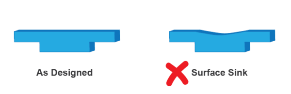
Sink
Plastic cools from the outside in and will always exhibit some degree of shrink upon ejection from the mold. Uneven shrinking, however, will often happen in thicker sections of the part because thicker sections take longer to harden and instead of pulling from neighboring thin and already hardened sections, they must pull from the surface. This creates a depression in the surface of the part, and, if it is severe enough, will become a point of stress and weakness in the part. This problem may be solved by increasing holding time post-injection or increasing the mold pressure. However, this error may sometimes call for a redesign of your part to adjust thickness. The easiest redesign solution is to build in a thickness transition, such as a slope or intermediate steps that will transition the part from thick to thin sections with less of an abrupt change that makes sink more likely to occur.
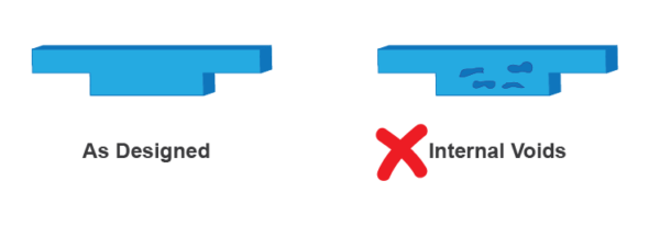
Voids
Voids may be considered a type of short shot because they are areas where material did not fill in the entire mold. However, voids are the product of air pockets and are not always visible. Rather, they may occur within the walls of the part, and depending on the size, number, and location of the voids, a part’s integrity may be compromised. This type of defect usually occurs when there is not enough pressure and air becomes trapped in the mold. Abrupt wall thickness changes may also be a factor because material in thin sections will cool faster than in thick sections and may harden before the thicker areas have been properly filled. Additionally, as plastic cools, it shrinks, which may also draw in air. In order to prevent voids, you can change the mold’s holding temperature, choose material that is less susceptible to shrink, redesign the part’s intended wall thickness, and move gates so thicker sections will fill first during the mold cycle.

Warp
If a part is coming out bent or twisted, this is a sign of internal or external stress on the part. Internal stress can form in the same fashion as sink marks. When thinner walls next to a thicker wall cool first, the thicker wall may pull on the adjacent thinner areas as it cools. This can cause the thinner section to bow or otherwise permanently deform. External stress may arise during ejection if the part’s designed draft angle is insufficient, causing it to drag along the sides of the mold. This friction, paired with the ejection force, may distort the part. Warping can be a serious problem because your part may not fit or function as desired. To prevent warp, cooling time and material temperature should be checked and adjusted as needed to avoid uneven shrinking. Uniform wall thickness should be used throughout the part, and/or walls should be supported with ribs and gussets. You may also consider using a material that is less susceptible to shrink and increasing the draft angle.
Weld Lines
A weld line is a thin line that appears on parts where separate material flows meet but do not bond together completely. This can happen when material leaves the gate and meets a barrier or partition that makes the flow split into different directions. If the two flows are moving too slowly and begin to cool before meeting back up, they will not bond correctly. This will appear as a line on the surface of the part and may be an area of weakness depending on its location. Weld lines can be avoided by increasing the molding temperature of the material and/or mold so the flow stays consistent. Alternate options include eliminating partitions, increasing injection speed, and switching to a lower viscosity material.
Injection Molding at 3 Space
Here at 3 Space, we offer multiple manufacturing services, including injection molding, thermoforming, and more. If you have questions about our process or need help designing or validating your design for manufacture, our engineers are happy to help guide you. For more information, contact us today.