Injection molding is the fastest mass manufacturing process available for plastic parts. As such, you can get your parts to consumers faster and cheaper than any other method. However, designing your parts to be injection molded can be quite tricky if you don’t know the best practices for this specific process. In this article, we’ll cover the injection molding process, design concerns, and common injection molding design problems.
The Injection Molding Process
Injection molding is a mass manufacturing process that uses a mold to rapidly produce many identical parts. While both plastic and metal can be injection molded, this article will focus on plastic injection molding.
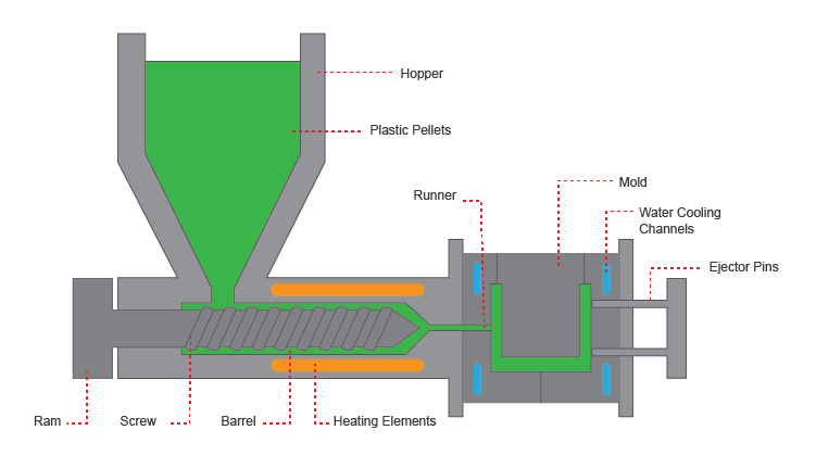 To produce a part via injection molding, plastic pellets of your chosen material are fed through a hopper down into the barrel of the machine. A ram and screw mechanism then pushes the pellets toward the heated end of the barrel where they begin to melt. Once the pellets are melted, the liquid plastic is pushed through the nozzle of the barrel and into the mold cavity. Through the use of water cooling channels around the mold, the plastic can quickly cool and solidify so that it holds the shape of the mold. The mold is opened, and ejector pins push the part out of the mold cavity. The mold closes again so that it is ready for the next injection. This is considered one mold cycle. Depending on the material and the size and design of the part, a mold cycle can take as little as two to five seconds.
The injection molding process is pretty straightforward, but it can only perform as well as the part is designed. Knowledge of best practices for injection molding and careful design of your part are crucial to producing the level of quality you desire. Poor part design can lead to big problems, such as sink, warp, or voids. Additionally, if your part design cannot be easily ejected from the mold, it can cause damage to the part or mold itself. If this happens or you have to do a redesign that will require a new mold to be milled, this can cost thousands of dollars and hundreds of hours to correct. Below, we discuss the main concerns with injection molded part design and provide tips on how to avoid the pitfalls of poor design.
Wall Thickness
Although it seems that walls should be simple to design, there are some precautions engineers should take into consideration when building their walls. Walls should always have uniform thickness or, at least, a gradual transition from one thickness to another to avoid sink, warp, and voids. Thicker walls take more time to cool and solidify, thus making your mold cycle longer and more costly. On the other hand, walls that are too thin may be damaged or broken during ejection from the mold. There is no hard and fast rule on wall thickness, however, because the minimum thickness will depend on what plastic you are using.
Coring
 To accommodate for areas of a part that need to be thicker, you can choose to core, or hollow, the section. This is done by, essentially, scooping out the inside of the thick area and replacing it with ribs or gussets. Ribs and gussets can offer support to the exterior walls to give you the same sturdiness as solid interior. This also provides the benefits of keeping wall thickness uniform, making the part more lightweight, and using less material so you can keep costs low.
Ribs & Gussets
 Ribs and gussets are features that are used to add rigidity and support in most parts. Their strategic placement can aid in a part’s load bearing stability, making your part stronger while avoiding thicker walls. The rib-to-wall ratio of thickness is important for avoiding sink as the point where a rib connects to a wall is a significant area where unintentional sink can occur.
Rounded Edges
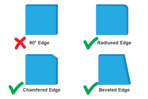 Sharp corners are prime areas for stress and breakages to occur. Often, it can be difficult for the molten plastic to properly fill a sharp angle, which may create a void in the part. To avoid these problems, it is not recommended to design your part with sharp corners. Instead, replace them with chamfers, bevels, or radiused edges. The main thing to remember is to keep your wall thickness uniform all the way around the curve so that no possibilities for sink arise.
Draft Angle
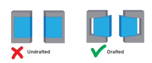 A draft angle is a slant that is applied to the walls and features of your part to allow for easy ejection from the mold. By utilizing a draft angle, a simple push of the ejector pins will pop the part out of the mold. Without a draft angle, your part is likely to drag along the sides of the mold, damaging the part and possibly the mold. Additionally, having a zero draft angle can cause a vacuum to form when ejecting the part, which can warp the part and requires more force to remove.
Bosses
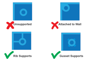 Bosses are hollow cylindrical features that are used to house fastening hardware, such as thread inserts or screws. They can be placed anywhere as needed, but there are a few things of which to be aware. Bosses always need some type of support to prevent breakage. However, they should not be attached to walls as this will make the walls too thick. When close to a wall, a rib should be used to connect it to the closest wall. This will keep wall thickness uniform while still supporting the boss. In the event that a boss is isolated away from walls, gussets should be used to support it. An additional practice to help prevent breakage is to make the base’s connection with the part radiused. Finally, the core of the boss should extend all the way to the base. Making the core too long or too short creates problems with wall thickness.
Crush Ribs
Press-fit parts can be difficult to manage when injection molding dictates that most surfaces, including holes, be drafted. However, there is a viable solution called crush ribs. Crush ribs are small protrusions used to secure press-fit parts. These features have a small surface area and do not need to be drafted. When a part is pressed onto the crush ribs, they deform just enough to create a firm hold. This helps ensure that you get both a clean ejection from the mold and a secure fit for press-fit parts.
Text
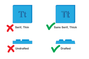 Text, symbols, and logos can be embossed or debossed in injection molding. However, there are several considerations to keep in mind during the design phase in order to ensure your text appears the way you want. First, text is embossed the majority of the time. This is because it is more expensive to carve metal from around letters in the mold to create debossed text. Debossed text also shortens the life of the mold since it would have small protrusions that could wear down or get damaged. Second, the text you use should be large and thick enough for your material to easily flow into the cavities made in the mold. To avoid filling problems, it is recommended to use a font that is sans-serif and has uniform letter thickness. Doing so will ensure that there are no tiny spaces your material must fill. Third, as with most surfaces of a part, the text will also have to be drafted. Because of this, it is important that your text should not be too tall because the draft will make the tips too thin, making them easier to break off.
Common Problems with Poor Design
Stress in a part often comes from poor design and shows up in the forms of sink, warp, voids, and other common defects. These stress creators can appear individually or simultaneously. Below, these main three are described in detail, along with tips on how to prevent them from happening in your part.
Sink
 Plastic shrinks as it cools, and uneven shrinking can create stress in the part. Because plastic cools from the outside in, thick sections will take longer to harden and can pull the surface inward. This causes cosmetic deformation and, often, stress because the dip becomes a point of weakness for the part. To best avoid sink marks, use uniform wall thickness throughout the entire part or transition well from thin to thick areas to prevent the shrinking from pulling in on one point in the surface. Also, ribs are a prime area for sink to occur. Take care to ensure that the base of a rib does not thicken the wall to which it connects.
Warp
 Warp is when a part becomes bent or twisted upon ejection from the mold. This happens due to variation in wall thickness. Thinner walls will cool before thicker ones, and the shrinkage that occurs in the thicker walls will pull on the solidified thin walls. If the pull is severe enough, this can cause a part to not fit or function correctly. Parts may even break due to warp. To avoid warp, adhere to the recommended wall thickness for your material and ensure uniform thickness.
Voids
 Voids are gaps in the part where the molten plastic was not able to properly fill the mold. These can occur in sharp corners where air can become trapped, preventing the plastic from filling the space. Additionally, where thin walls change to a thick section, the thin walls may cool and solidify before the plastic has had the chance to completely fill the thicker space. This often happens at the conjunction of a rib and a wall. To prevent voids, follow the recommendations on wall thickness and rounded corners.
Manufacturing at 3 Space
Here at 3 Space, we can help with many manufacturing needs, including part design, 3D scanning, part inspection, 3D printing, injection molding, and more. Our technicians have years of experience, which will ensure you get the best service possible. If you’re unsure whether your part is properly designed for injection molding, we can take a look and assist you in any necessary design changes. Additionally, we can suggest alternatives if injection molding doesn’t suit your exact production needs. For more information, contact us today.