Digital 3D models are used for many different purposes in a variety of industries, and there are multiple methods of making them from a real object. The two primary methods for digital 3D modeling are 3D scanning and photogrammetry. In this article, we’ll discuss the process, advantages, and disadvantages of each technology as well as some common applications for this type of digital 3D modeling.
3D Scanning
3D scanning encompasses a variety of technologies. For sake of comparison, we have chosen to focus on the two varieties of 3D scanning that are most common and most resemble the abilities of photogrammetry: laser 3D scanning and structured light 3D scanning.
Laser 3D Scanning
Laser 3D scanning is a technology that uses a laser to take measurements of an object’s geometry and create a digital 3D model from this acquired data. This is done by running a laser point or line along every surface of the part to capture measurements from multiple viewpoints, which translates to thousands of data points in a specialized computer software.
There are two types of laser 3D scanners, and they differ from each other in how they calculate a part’s measurements. The calculations can be done via two different methods: triangulation and time-of-flight.
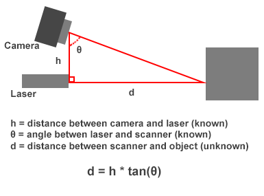 Triangulation works by using simple trigonometry. The laser on the scanner is paired with a camera, making them two vertices of a triangle. The third vertice, which completes the triangle, is the point on the object that is being scanned. Because the distance between the laser emitter and camera is known, as well as their angle relative to each other, the distance to the point of contact on the object being scanned can then be calculated and recorded.
As for a time-of-flight laser 3D scanner, a pulse of laser light is emitted at the object being scanned. Once the light makes contact with the object and returns to the sensor on the scanner, the scanner will calculate the location of the point based on how long it took the light to travel from the laser emitter to the object and back. This can be done because the speed of light is a known constant.
Once the measurements are captured and recorded by either 3D scanner, a point cloud of all the measurements is created. Each of the thousands of individual data points are connected to others with lines so that triangles are formed, making a polygonal mesh that can then be used for various 3D modeling and design purposes.
Structured Light 3D Scanning
Another way to scan your part for digital modeling is structured light 3D scanning. This scanning method utilizes an LCD projector and at least two cameras to map a part’s geometry. The projector projects patterns of light, typically alternating light and dark stripes, onto the surface of the part to be scanned. The cameras of the scanner then record the part’s geometry by measuring where and how the light pattern deforms around the part and creates data points to 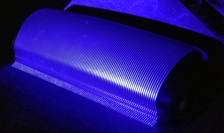 match. To capture every angle of the part, the part may be rotated or the scanner moved around it. Another scan is taken with every rotation, and the data points acquired are sent to the computer. The scans automatically align due to tracking stickers placed on the part, giving the software reference points to match each scan up to one another. The end result is a polygon mesh just like with laser 3D scanning.
It is important to note that there are two different types of structured light 3D scanners: white light and blue light.
Pros & Cons
There are several advantages to using 3D scanning. Most notable is its extreme accuracy and high resolution that makes it reliable for reverse engineering CAD straight from a scan’s mesh file. It performs especially well with smaller parts where accuracy is required. Since 3D scanners typically have a small field of vision, there is more focus put on the visible area so a high accuracy can be achieved.
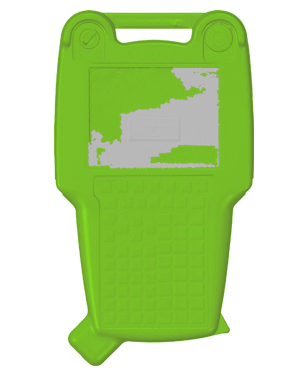 In addition to this, 3D scanning software creates data points in real time so you are able to see which areas of the part have already been scanned, which have been missed, and which need to be rescanned. This lends itself to efficiency so you will not get into the design phase and realize you need more scan data.
As for some areas where 3D scanning lacks, light interference can make this technology produce unfavorable scans. This is because both laser and structured light 3D scanners read a light source in order to collect the necessary data. If there is too much ambient light, the resulting data may be distorted or noisy. As such, 3D scanning is best used in a room where the lighting can be controlled. Although 3D scanning can be used outdoors, it can be a challenge to get satisfactory results due to excess light.
In relation to light interference, 3D scanning may have trouble with shiny/reflective, black, and transparent surfaces because the light put out by the scanner is liable to become distorted when it comes into contact with these types of surfaces. However, you can always coat your part with a washable paint that will prevent the surface from being an issue.
Finally, for 3D scanning, the scanner alone can cost you tens of thousands of dollars. Also, in order to upgrade to keep up with technology advancements, you will need to purchase a new scanner rather than just new software to avoid becoming obsolete.
Photogrammetry
Photogrammetry is another method of recording a part’s geometry to create a 3D model. As opposed to 3D scanning, this technology uses photographs rather than light to gather data. In addition to requiring a camera of your choice, this technology needs a computer and specialized software in order to create a 3D model.
 To make a 3D model via photogrammetry, many photos are taken of the object you wish to model. These photos are taken from different angles to capture each part of the part’s geometry and must overlap slightly from one photo to the next, much like the scans taken via structured light 3D scanning. This overlapping is what allows the photogrammetry software to later align the photos.
On average, 100 photos are needed to get enough data for a good model. This can be time-consuming if you are using a single camera because you must rotate the part or move the camera around it to snap one photo at a time. This becomes easier if you have a multi-camera setup.
Once all the photos have been taken, they are imported into the software to be aligned. The software does this by using image processing to find reference points in the texture of the overlapping photos. From this alignment of all of the photos, the software can then plot data points using triangulation to calculate the distance and location of each feature in three-dimensional space. This forms a point cloud so that the software can create a polygon mesh just like 3D scanning.
Pros & Cons
The primary advantage of using photogrammetry for 3D models is its excellent ability to reproduce an object in full color and texture. While some 3D scanners can do this, photogrammetry lends itself to this purpose more due to its photographs producing realism.
Additionally, photogrammetry is easily accessible to most people because the equipment and software is nowhere near as expensive as 3D scanning. For the most part, any digital camera will work for photogrammetry, so you have more options when choosing your equipment. The technology also does not suffer from high upgrade expenses as 3D scanning can. To upgrade photogrammetry, you usually just need to invest in new software updates.
Along with these advantages, photogrammetry also comes with many drawbacks. Because the texture of a part is what allows photogrammetry to make reference points, it can be challenging to work with parts that have a smooth, flat, and/or solid-colored surface. To fix this, some industry advisers recommend altering the surface of the object, such as adding a powder to the part. Unfortunately, this can be hazardous for many reasons, including the desire to keep the part in original condition and the result that the measurements will be thrown off this way.
Photogrammetry can also prove to be disadvantageous if you do not have a multi-camera setup. Working with one camera may be time-consuming as you must rotate the part or manually move the camera around the part. In addition to this manual movement, you must also make sure not to miss any sections of the part. Photogrammetry does not build the model in real time as 3D scanning does, meaning you must take the photos and import them all before you can know if you missed a section or need to redo an area. This can result in time lost because you have to return to the object site or set up the part again to take more photos.
Finally, it is important to note that photogrammetry has a lower accuracy than 3D scanners. This is caused by several factors, including photo resolution, camera calibration, angles, redundancy, and more. To put it simply, if your chosen camera has a low resolution or has not been calibrated precisely, your measurements will not be as accurate as possible. While 3D scanners also need to have high resolution and calibration, these two factors are more controlled for 3D scanners because there are fewer choices for equipment, so data collected will be more precise. Additionally, photogrammetry performs better when a feature appears in more than two photos and is photographed from vastly different angles with 90 degrees being the preferred difference from the first angle to the second and so forth. If the angles are too close together or the feature appears in too few of photos, the software may not be able to accurately plot the data points needed to recreate these parts of the object.
Applications
When deciding whether 3D scanning or photogrammetry is a better match for your project, the main factor to consider is the area size you’re wanting to model and what level of accuracy you need. Below are some examples to show where one technology is more useful than the other depending on these two factors.
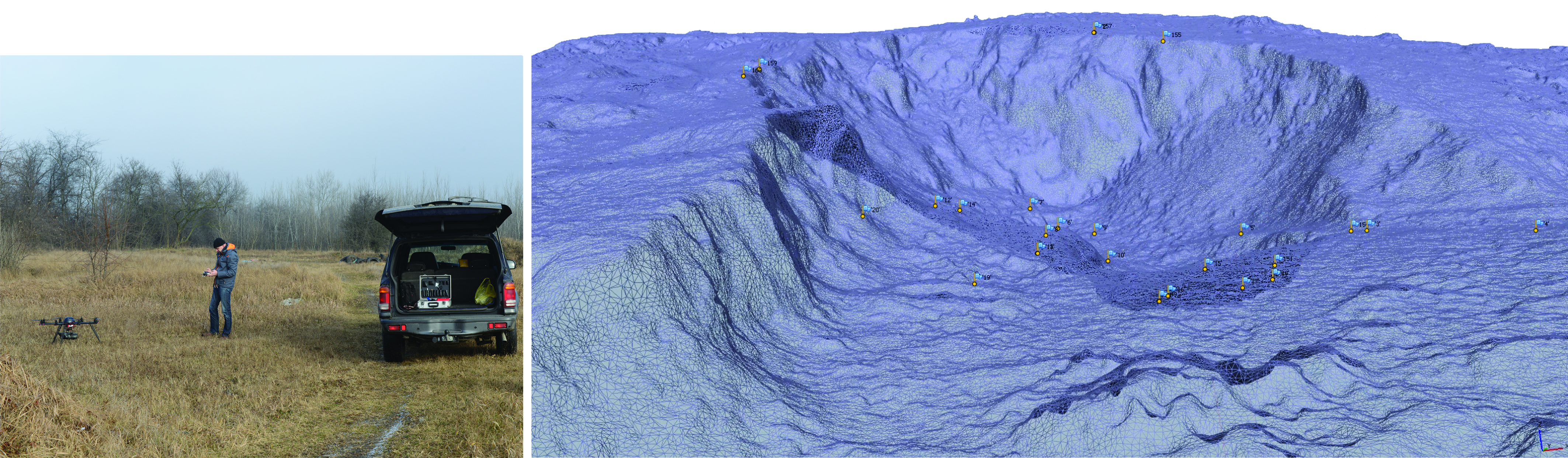 Topography
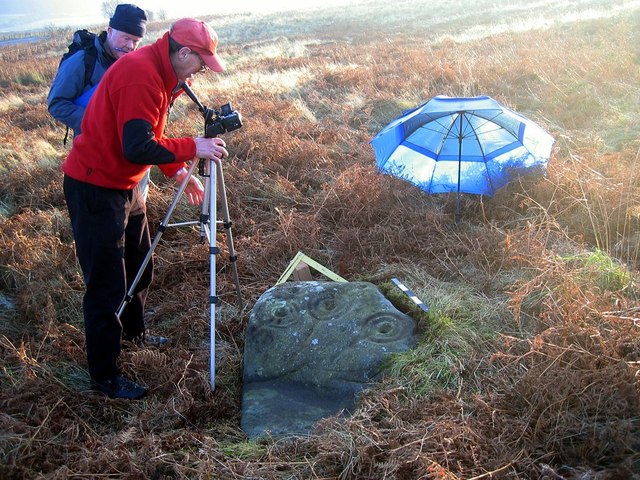
Landscapes are often rendered as 3D models for many reasons, including use as interactive maps, archaeology dig site surveys, and videogame and movie graphics. Because realism is more important than extreme accuracy in topography, photogrammetry is often used for this purpose. While 3D scanners could potentially perform the same task, they are more susceptible to light interference, especially harsh sunlight, and have a much smaller field of vision than photogrammetry. While you may have to work around weather and avoid sharp shadows with photogrammetry, it far surpasses 3D scanning for recreating an environment as a 3D model.
Reverse Engineering
When designing a part, accuracy matters most. This is especially true if you are reverse engineering a piece and need to match it exactly. For this high level of 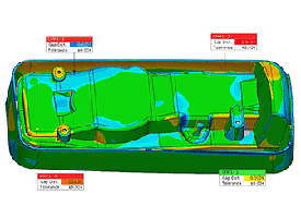 accuracy, you will need 3D scanning. With photogrammetry, even small inaccuracies can lead to big mistakes or skewed measurements overall in a design, such as with architecture design.
Part Inspection
It is also best to use 3D scanning for part inspection for the same reasons as reverse engineering. To make sure your parts meet your standards, high accuracy is crucial. If a lower accuracy technology, such as photogrammetry, is used, your measurements may give you unreliable results.
3D Scanning at 3 Space
Here at 3 Space, we offer a variety of 3D scanning services, including both laser and structured light 3D scanning. If you are unsure whether 3D scanning or photogrammetry will better suit your needs, our engineers are happy to suggestions on which is right for you. For more information, contact us today.